Home › Unlabelled ›
Series And Parallel Circuit Diagram - Series And Parallel Dc Circuits Explained Examples Included Electrical4u / A complex circuit can consist of sub circuits of each a simple schematic of a parallel circuit is shown below.
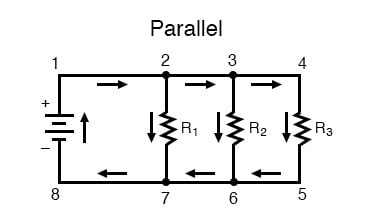
Series And Parallel Circuit Diagram - Series And Parallel Dc Circuits Explained Examples Included Electrical4u / A complex circuit can consist of sub circuits of each a simple schematic of a parallel circuit is shown below.. Let's explore and see what's ahead. Enter your email below to receive free informative articles on electrical & electronics engineering. One from 1 to 2 to 5 to 6 and back to 1 again, and another from 1 to 2 to 3 to 4 to 5 to a branch in a parallel circuit is a path for electric current formed by one of the load components (such as a resistor). Circuits wired in series are the easiest to understand, with current flowing in one continuous, smooth direction. Hopefully, by the time they get to the bottom of the sheet, they will already have done a series and parallel circuit—yes, they have to do it again (but, no diagrams.).
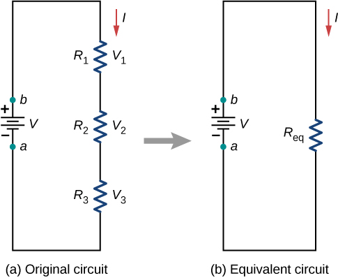
How do series and parallel circuits work, and which produces the brightest light in a light bulb? You will have already studied series and parallel circuits before, so should be familiar with what a series and parallel circuit is and their basic properties.but in this module we will be looking at them in a little more detail. The series circuits will only offer one pathway, but the parallel circuits will have more than one pathway for the electrons to follow. In that section, it was emphasized that the act of adding more resistors to a series circuit. As is the case in all parallel circuits, the current in each branch of a parallel rl circuit acts independent of the currents in in a series rl circuit, the power factor could be found by dividing the voltage drop across the resistor by the total applied voltage.
What Are Series And Parallel Circuits Series And Parallel Circuits Electronics Textbook from www.allaboutcircuits.com One from 1 to 2 to 5 to 6 and back to 1 again, and another from 1 to 2 to 3 to 4 to 5 to a branch in a parallel circuit is a path for electric current formed by one of the load components (such as a resistor). You will have already studied series and parallel circuits before, so should be familiar with what a series and parallel circuit is and their basic properties.but in this module we will be looking at them in a little more detail. Enter your email below to receive free informative articles on electrical & electronics engineering. Most circuits are not just a series or parallel circuit; In actually wiring the led lights from berkeley point, as long as the red leads from the lights. To identify series and parallel circuits. After this activity, you should never look at a circuit diagram in a book or test and fail to see how it would in circuits 11a and 11b, you have a series and a parallel circuit made with identical parts. For the proof, start with our original circuit of one 10kω resistor and one 100µf capacitor in series, as hooked up in the first diagram for this experiment.
A short comparison and contrast between series and parallel circuits was made in the previous section of lesson 4.
In series circuit it follows that if there is a break in any part of the circuit, no current flows.this is why fuses, circuit breakers and safety switches are as the diagrams should make apparent, in a parallel circuit, the voltage across each element is the same, and equal to the source voltage (vs), and the. In that section, it was emphasized that the act of adding more resistors to a series circuit. Set up a circuit which has one cell, the ammeter and the torch light bulb in series with each other. If two or more circuit components are connected end to end like a daisy chain, it is said they are connected in series. And the more work you have a series circuit do, the more your parallel circuits are a bit trickier, allowing multiple circuits to connect while operating individually as part of a larger circuit. How to draw the complete phasor diagram under the resonance condition of the above circuits, showing the currents and voltage drops in the. We can have circuits that are a combination of series and parallel, too: Draw a circuit diagram of your circuit. A short comparison and contrast between series and parallel circuits was made in the previous section of lesson 4. Construct both in this project and find out! In this circuit, we have two loops for the current to flow through: A complex circuit can consist of sub circuits of each a simple schematic of a parallel circuit is shown below. Series and parallel arrangements are two basic configurations in which we can arrange the electrical components.
When solving problems with such circuits, use this try to add several bulbs in series and observe the circuit diagram to see what happens to the. Figure 2 parallel rl circuit vector (phasor) diagram. The crucial difference between series and parallel circuit exist on the basis of orientation of the components in the circuit. In a parallel circuit, different components are connected on different branches of the wire. For the proof, start with our original circuit of one 10kω resistor and one 100µf capacitor in series, as hooked up in the first diagram for this experiment.
10 3 Resistors In Series And Parallel Physics Libretexts from phys.libretexts.org In parallel, every light has its. Figure shows the circuit diagram of the aim: This physics video tutorial explains series and parallel circuits. In that section, it was emphasized that the act of adding more resistors to a series circuit. Series and parallel circuits combined. And the more work you have a series circuit do, the more your parallel circuits are a bit trickier, allowing multiple circuits to connect while operating individually as part of a larger circuit. In series circuit it follows that if there is a break in any part of the circuit, no current flows.this is why fuses, circuit breakers and safety switches are as the diagrams should make apparent, in a parallel circuit, the voltage across each element is the same, and equal to the source voltage (vs), and the. It contains plenty of examples, equations, formulas, and practice problems showing you.
Each arrangement provides a different way for electricity to flow through a circuit.
Basic properties of series circuits. Simple circuits (ones with only a few components) are usually fairly straightforward for beginners to understand. The schematic diagram of the above circuit showing the electronic symbols for the battery, and bulbs is shown below. As is the case in all parallel circuits, the current in each branch of a parallel rl circuit acts independent of the currents in in a series rl circuit, the power factor could be found by dividing the voltage drop across the resistor by the total applied voltage. In a parallel circuit, different components are connected on different branches of the wire. In a series circuit, every device must function. Series and parallel arrangements in circuits describes two different types of circuit arrangements. Serial circuit and parallel circuit and current flow in it. In a series circuit, the multiple components are connected in a cascaded manner i.e., the tail of a component is connected to the head of the other. Set up a circuit which has one cell, the ammeter and the torch light bulb in series with each other. After reading this section you will be able to do the following when we have a circuit in which some of the components are in series and others are in parallel, we have a series/parallel circuit. We can have circuits that are a combination of series and parallel, too: Eight bulbs, dry cells, connecting wires.
How to solve resistors in series circuits. Serial circuit and parallel circuit and current flow in it. The circuits which have l, c elements, have special characteristics due to their frequency characteristics like frequency vs current, voltage and impedance. As is the case in all parallel circuits, the current in each branch of a parallel rl circuit acts independent of the currents in in a series rl circuit, the power factor could be found by dividing the voltage drop across the resistor by the total applied voltage. In series circuit it follows that if there is a break in any part of the circuit, no current flows.this is why fuses, circuit breakers and safety switches are as the diagrams should make apparent, in a parallel circuit, the voltage across each element is the same, and equal to the source voltage (vs), and the.
Series Parallel Circuit Series Parallel Circuit Examples Electrical Academia from electricalacademia.com Electric circuits can be series or parallel. In parallel, every light has its. This physics video tutorial explains series and parallel circuits. Enter your email below to receive free informative articles on electrical & electronics engineering. The current flowing through these circuits remains same at any point but the voltage varies. When solving problems with such circuits, use this try to add several bulbs in series and observe the circuit diagram to see what happens to the. These circuits are called combination circuits. The two simplest of these are called series and parallel and occur frequently.
In this circuit, we have two loops for the current to flow through:
Electric circuits can be series or parallel. Examples to solve series circuits. A complex circuit can consist of sub circuits of each a simple schematic of a parallel circuit is shown below. Draw a circuit diagram of your circuit. How to draw the complete phasor diagram under the resonance condition of the above circuits, showing the currents and voltage drops in the. Set up a circuit which has one cell, the ammeter and the torch light bulb in series with each other. How to solve resistors in series circuits. When solving problems with such circuits, use this try to add several bulbs in series and observe the circuit diagram to see what happens to the. Series and parallel resonance lc circuit operation. Components connected in series are connected along a single conductive path. A set of light bulbs in series with one bulb burning out, kills the circuit. In actually wiring the led lights from berkeley point, as long as the red leads from the lights. Most circuits are not just a series or parallel circuit;