Home › Unlabelled ›
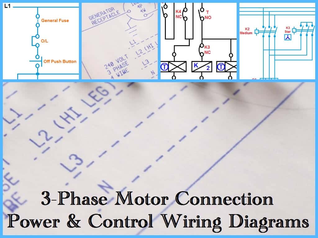
Star Delta Starter Control Circuit Diagram With Timer - The Beginner S Guide To Wiring A Star Delta Circuit Factomart Singapore : In my last post, i share a star delta starter wiring diagram 3 phase motor connection.
Star Delta Starter Control Circuit Diagram With Timer - The Beginner S Guide To Wiring A Star Delta Circuit Factomart Singapore : In my last post, i share a star delta starter wiring diagram 3 phase motor connection.. In control wiring diagram all magnetic contactors coils are rated 220 vac. Star delta wiring diagram electrical engineering updates. Auto transformer starter diagram, control circuit, working, autotransformer starter wiring diagram, autotransformer starter working. In this post, you will learn complete star delta starter wiring with timer, normally open push button switch, and normally close push button switch. So this time i want share my simple star delta circuit diagram completed with power and control line circuiti hope it can be as basic reference for all electrician about.
It's not 100% accurate but at lease we can get the approximate time for change over timer of star delta starter.normally the base line for timer setting is around 10 until 20 second. So this time i want share my simple star delta circuit diagram completed with power and control line circuiti hope it can be as basic reference for all electrician about. In the above star delta starter control circuit wiring diagram with timer and normally close push button/normally open push button switch. Controlling the interchanging star connection and delta connection of an ac induction motor is achieved by means of a star delta or wye delta control circuit. A star delta starter is a type of reduced voltage starter.we use it to reduce the starting current of the motor without using any external device or apparatus.
45a7 Star Delta Starter Control Wiring Diagram With Timer Pdf Wiring Resources from www.electricaltechnology.org Lathes millers grinders shapers borers and other machine tool instruction operation and maintenance manuals handbooks and parts manuals. In the above star delta starter control circuit wiring diagram with timer and normally close push buttonnormally open push button switch. Star delta wiring diagram electrical engineering updates. It have different design and technique for the control circuit but the main objective is same,to reduce starting inrush current. As we have already shared the star delta y d 3 phase motor starting method by automatic star delta starter with timernow we are going to share three phase motor connection stardelta starter without timer power control diagrams. Power and #control circuit.star delta starter control circuit #diagram star delta control circuit s. Refer to the below star delta circuit, A star delta starter is a type of reduced voltage starter.we use it to reduce the starting current of the motor without using any external device or apparatus.
The control circuit uses to control the starter circuit such as on, off and tripping operations.
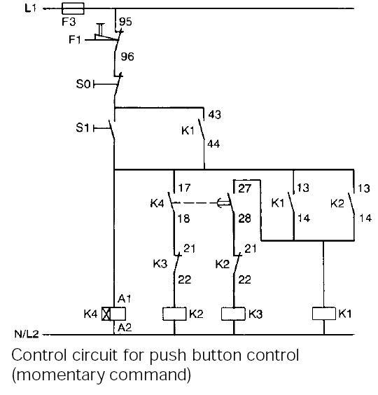
Star delta starter control circuit diagram is today's topic. Automatic star delta starter with timer wiring & installation diagram. In the control wiring diagram, all magnetic contactors coils are rated 220 vac. These two method that i'd explained above is a basic measurement technique that we can use to determine the approximate time for change over of star delta starter. R , y, b = red, yellow, blue ( 3 phase lines)c.b = general circuit breakermain = mai supplyy = starδ = deltac1, c2, c3 = contatcors (power diagram)o/l = over load relayno = normally opennc = normally closed k1 = contactor (contactor coil) k1/no = contactor holding coil. When the start push button is switch on in the external input terminal of the plc, its corresponding input terminal address x0 activates. Star delta wiring diagram electrical engineering updates. In the above star delta starter control circuit wiring diagram with timer and normally close push buttonnormally open push button switch. Always check with your manufacturer how, and if, a motor can be connected to a star delta starter. The control of the contactors is by the timer (k1t) built into the starter. The star and delta are electrically interlocked and preferably mechanically interlocked as well. Below are two examples of wiring diagrams for star delta starters from industry suppliers. To control the changeover from star to delta contactors we simply use a timer to control.
Star delta starter control wiring diagram with timer pdf. The control circuit uses to control the starter circuit such as on, off and tripping operations. A 8 pin timer is used. In a starter, closed contact (after receiving input) is used in the star side circuit and normally open contact is used in the delta side starter circuit. The on delay timer diagram is also shown in the diagram.
Plc Plc Ladder Plc Ebook Plc Programming Typical Circuit Diagram Of Star Delta Starter from 1.bp.blogspot.com A star delta starter is the most commonly used method for the starting of a 3 phase. Power and #control circuit.star delta starter control circuit #diagram star delta control circuit s. Refer to the below star delta circuit, Star delta starter control circuit wiring diagram consist timer, push button for start and stop. As we have already shared the star delta y d 3 phase motor starting method by automatic star delta starter with timernow we are going to share three phase motor connection stardelta starter without timer power control diagrams. The control circuit consists of push button switches, auxiliary contacts and a timer. Star delta starters consist of a power circuit and control circuit. Star delta starter diagram with connection of 3 phase motor and control circuit wiring.
Always check with your manufacturer how, and if, a motor can be connected to a star delta starter.
The star and delta are electrically interlocked and preferably mechanically interlocked as well. Star delta starter control circuit diagram is today's topic. Refer to the below star delta circuit, The main and the star contactors are closed and the delta contactor is open. These two method that i'd explained above is a basic measurement technique that we can use to determine the approximate time for change over of star delta starter. In the above star delta starter control circuit wiring diagram with timer and normally close push button/normally open push button switch. R , y, b = red, yellow, blue ( 3 phase lines)c.b = general circuit breakermain = mai supplyy = starδ = deltac1, c2, c3 = contatcors (power diagram)o/l = over load relayno = normally opennc = normally closed k1 = contactor (contactor coil) k1/no = contactor holding coil. It consists of two normally open contacts. A 8 pin timer is used. Star delta connection circuit diagram: Bill carey at bcarey at accessintel. Star delta starter wiring diagram this post is about the main wiring connection of three phase motor with star delta starter and control wiring diagram of star delta starter. R , y, b = red, yellow, blue ( 3 phase lines)c.b = general circuit breakermain = mai supplyy = starδ = deltac1, c2, c3 = contatcors (power diagram)o/l = over load relayno = normally opennc = normally closed k1 = contactor (contactor coil) k1/no = contactor holding coil.
The main and the star contactors are closed and the delta contactor is open. By the end of this tutorial you will understand how these work. R , y, b = red, yellow, blue ( 3 phase lines)c.b = general circuit breakermain = mai supplyy = starδ = deltac1, c2, c3 = contatcors (power diagram)o/l = over load relayno = normally opennc = normally closed k1 = contactor (contactor coil) k1/no = contactor holding coil. Lathes millers grinders shapers borers and other machine tool instruction operation and maintenance manuals handbooks and parts manuals. In the above star delta starter control circuit wiring diagram with timer and normally close push buttonnormally open push button switch.
Star Delta Starter Electrical Notes Articles from electricalnotes.files.wordpress.com Automatic star delta starter with timer wiring & installation diagram. The control of the contactors is by the timer (k1t) built into the starter. So this time i want share my simple star delta circuit diagram completed with power and control line circuiti hope it can be as basic reference for all electrician about. Star delta wiring diagram electrical engineering updates. Auto transformer starter diagram, control circuit, working, autotransformer starter wiring diagram, autotransformer starter working. In this post, you will learn complete star delta starter wiring with timer, normally open push button switch, and normally close push button switch. R , y, b = red, yellow, blue ( 3 phase lines)c.b = general circuit breakermain = mai supplyy = starδ = deltac1, c2, c3 = contatcors (power diagram)o/l = over load relayno = normally opennc = normally closed k1 = contactor (contactor coil) k1/no = contactor holding coil. Dosto aaj ki is video me aap dekheenge star delta starter control circuit diagram or kaise kaam karta hai #stardeltastartercircuit subscribe yk electrical fo.
Star delta starter control wiring diagram with timer pdf unknown 7:08 pm.
As shown in the fig. Star delta starter diagram with connection of 3 phase motor and control circuit wiring. R , y, b = red, yellow, blue ( 3 phase lines)c.b = general circuit breakermain = mai supplyy = starδ = deltac1, c2, c3 = contatcors (power diagram)o/l = over load relayno = normally opennc = normally closed k1 = contactor (contactor coil) k1/no = contactor holding coil. Star delta starters consist of a power circuit and control circuit. The on delay timer diagram is also shown in the diagram. A star delta starter is the most commonly used method for the starting of a 3 phase. A 8 pin timer is used. In this post, you will learn complete star delta starter wiring with timer, normally open push button switch, and normally close push button switch. Star delta starter control circuit diagram is today topic. In the above star delta starter control circuit wiring diagram with timer and normally close push button/normally open push button switch. To control the changeover from star to delta contactors we simply use a timer to control. In my last post, i share a star delta starter wiring diagram 3 phase motor connection. Bill carey at bcarey at accessintel.
Power and #control circuitstar delta starter control circuit #diagram star delta control circuit s star delta control circuit diagram with timer. In the above star delta starter control circuit wiring diagram with timer and normally close push button/normally open push button switch.